
SENTRY V3: Deployed Mechatronics Platform
The assembled SENTRY V3 pan–tilt turret platform (silent looping animation).
At a glance
- Status
- Deployed
- Context
- Educational · Open Source
- Timeline
- 2023–2025
- Role
- Architected and built the platform end to end — architecture, mechanical design, control electronics and PCB, and reference firmware; users' vision and targeting software runs on external compute
- Used by 100+ students per year in its U.S. Naval Academy instructional deployment
- Originated at the U.S. Naval Academy and released publicly as open source
- Subject of a selected Autodesk University 2025 presentation (From Schematics to Reality)
Canonical: Source on GitHub
Overview
SENTRY V3 is an embedded electromechanical platform that integrates sensing, actuation, and control for a pan-tilt robotic turret system. The platform combines custom motor control electronics, sensor interfaces, and embedded firmware to coordinate flywheel propulsion, ammunition feeding, and two-axis positioning. The design supports modular expansion and allows higher-level compute systems to command the platform while the embedded controller handles real-time motor control and safety behavior.
Problem
Earlier versions of the platform relied on ad-hoc wiring and distributed control logic, which made integration, testing, and debugging difficult. The V3 design consolidates motor control, sensor interfaces, and safety handling into a dedicated embedded controller, creating a more maintainable architecture for experimentation and development.
System Architecture
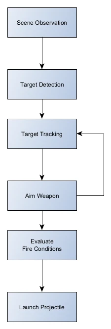
My Role
I architected and built the platform end to end. The parts of SENTRY that are mine:
- System and electromechanical architecture
- Mechanical design of the turret platform and enclosure
- Control electronics and PCB design
- Embedded reference firmware proving closed-loop operation, structured as a student-writable software interface
- Electromechanical integration, bring-up, and verification
- Technical documentation
Higher-level vision processing, targeting software, and autonomy experiments run on an external compute platform and are developed by the platform's users — faculty, researchers, and students — not by me. SENTRY originated at the U.S. Naval Academy and was released publicly by the institution; I independently maintain the hardware, PCB, and mechanical design.
Hardware Design
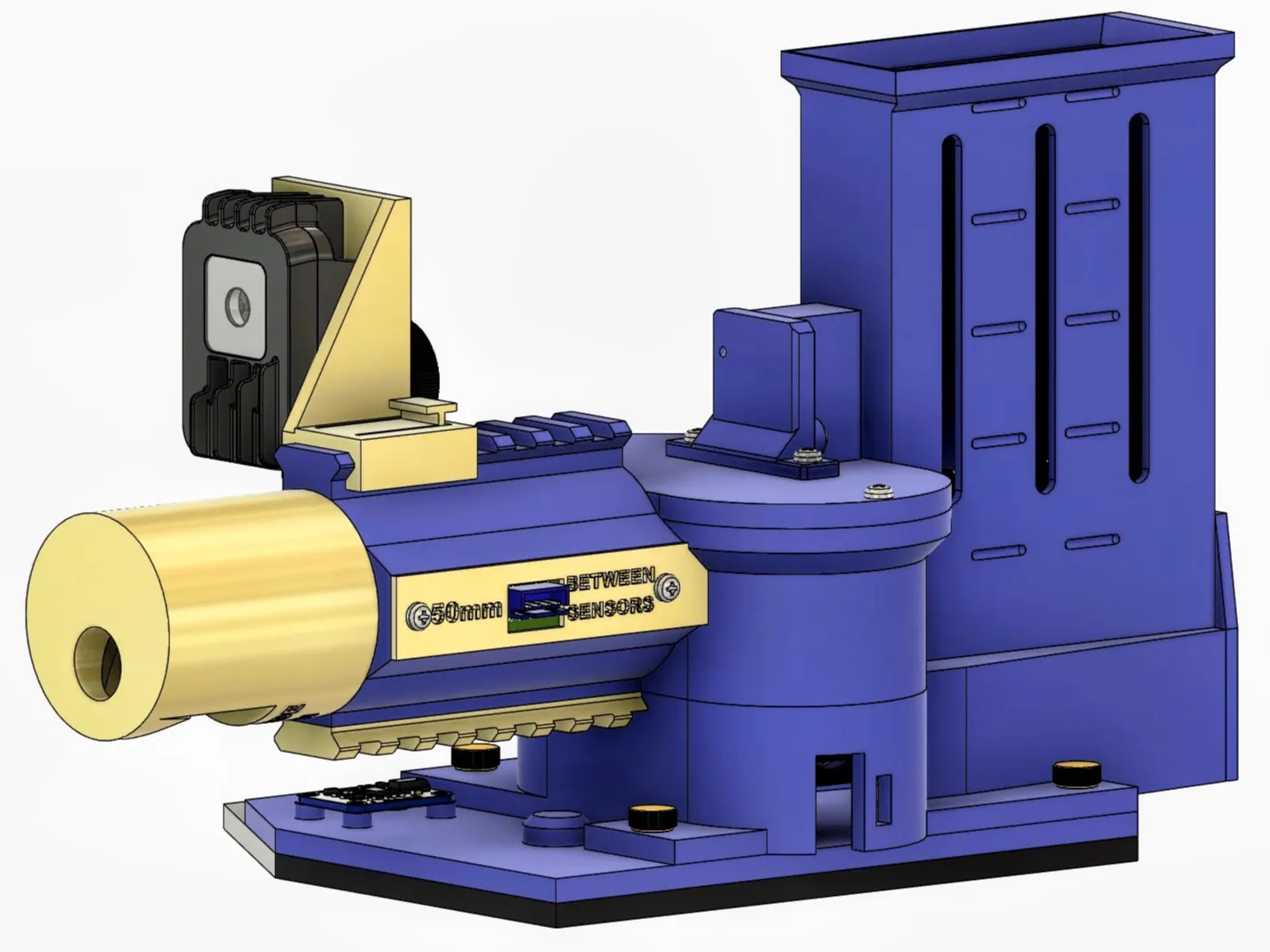
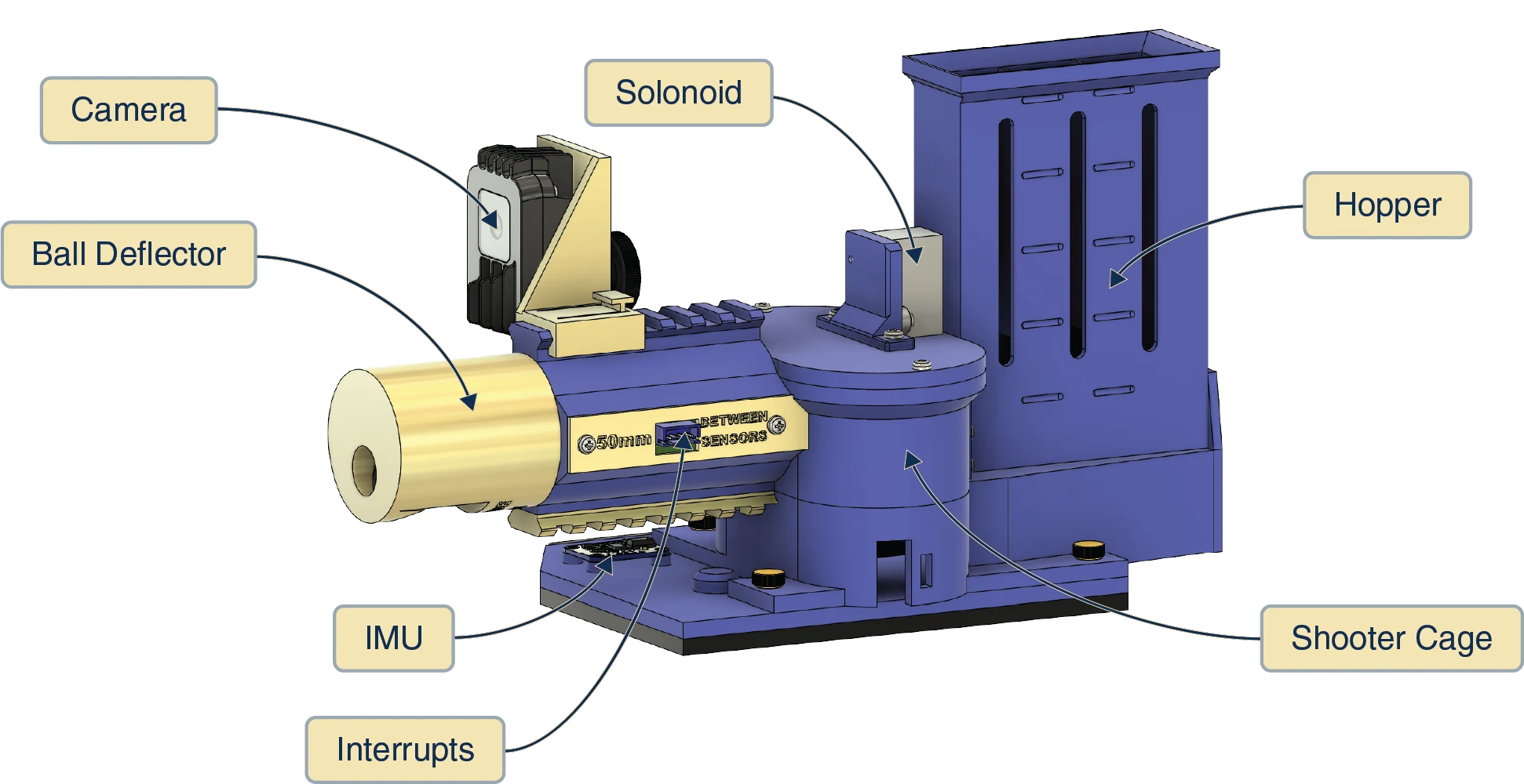
The mechanical and electrical design of SENTRY V3 was developed together so the control board, drivetrain, sensor placement, and service access all supported reliable integration. The platform layout emphasizes subsystem separation, maintainable wiring, and clear mechanical paths for actuation and feed components.
CAD assembly overview
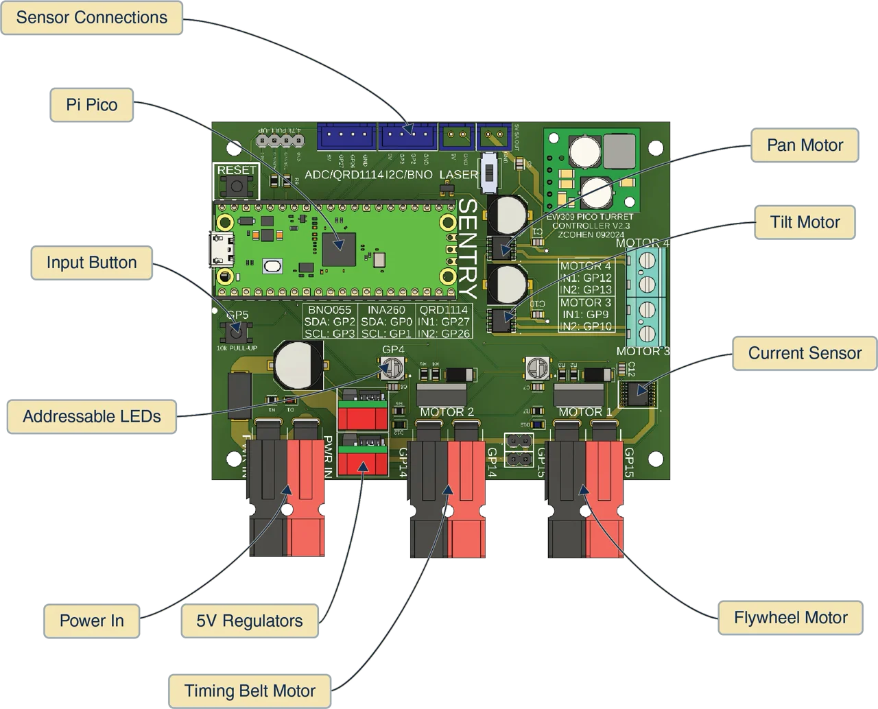
Labeled subsystem view
Interfaces
- Power interfaces: Single DC input supplying the platform, with onboard regulation providing local 5 V and 3.3 V rails for logic, sensors, and motor drivers.
- Data interfaces: I²C bus for onboard sensors and analog expansion, along with USB or serial communication to an external host computer used for higher-level control and perception.
- Control interfaces: PWM and digital GPIO used for motor drivers and actuators, with additional GPIO inputs for system triggers and safety control.
Key Design Decisions
- Decision: Separate high-level control from real-time motor control. Rationale: Allow external compute systems to handle perception and targeting while the embedded controller manages timing-critical motor control and safety behavior.
- Decision: Use a microcontroller-based control board (RP2040) for actuator coordination. Rationale: Provide deterministic timing for motor control, sensor polling, and actuator sequencing without relying on a general-purpose host computer.
- Decision: Place sensors and auxiliary devices on a shared I²C bus. Rationale: Reduce wiring complexity and allow new sensors to be added without redesigning the control architecture.
- Decision: Use discrete motor drivers for pan, tilt, flywheel, and feed mechanisms. Rationale: Allow each subsystem to be controlled and tuned independently while simplifying debugging during bring-up.
- Decision: Integrate current monitoring on the flywheel drive. Rationale: Detect projectile events through current spikes, enabling reliable shot counting without additional sensors.
Implementation
- Custom control PCB integrating motor drivers, sensor interfaces, and power regulation for turret subsystems.
- Embedded firmware running on the RP2040 that coordinates flywheel spin-up, ammunition feed control, and pan–tilt positioning.
- I²C sensor integration for orientation and system monitoring, with current sensing used to detect projectile events during firing.
- Integration with an external compute platform responsible for vision processing and target selection while the embedded controller manages real-time actuation.
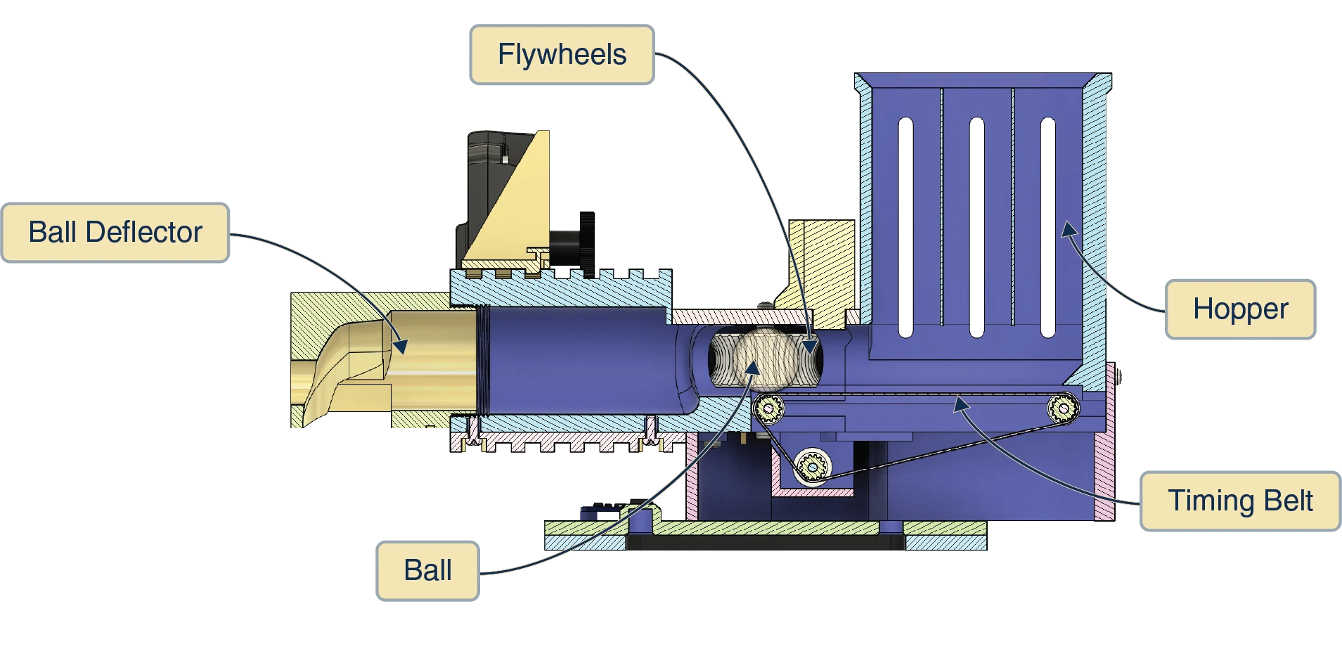
Cross-section view
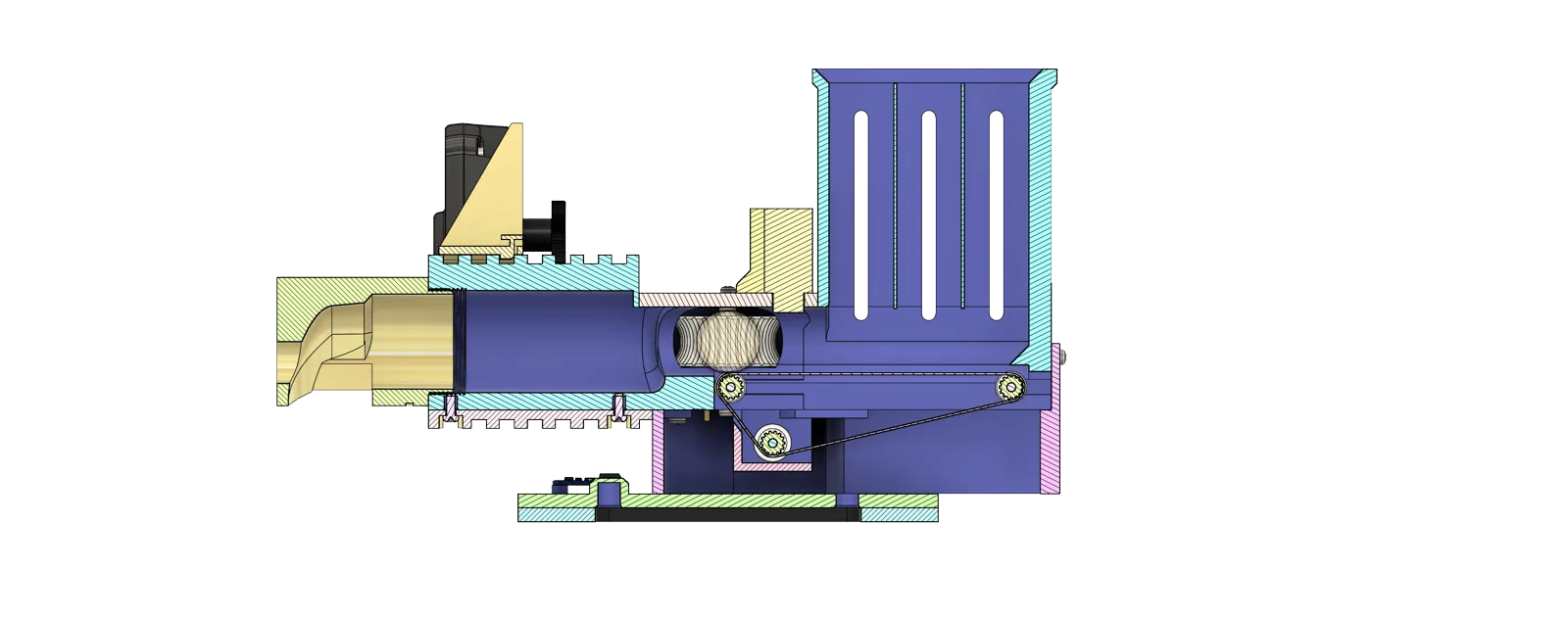
Labeled cross-section
Artifacts
Control board integration
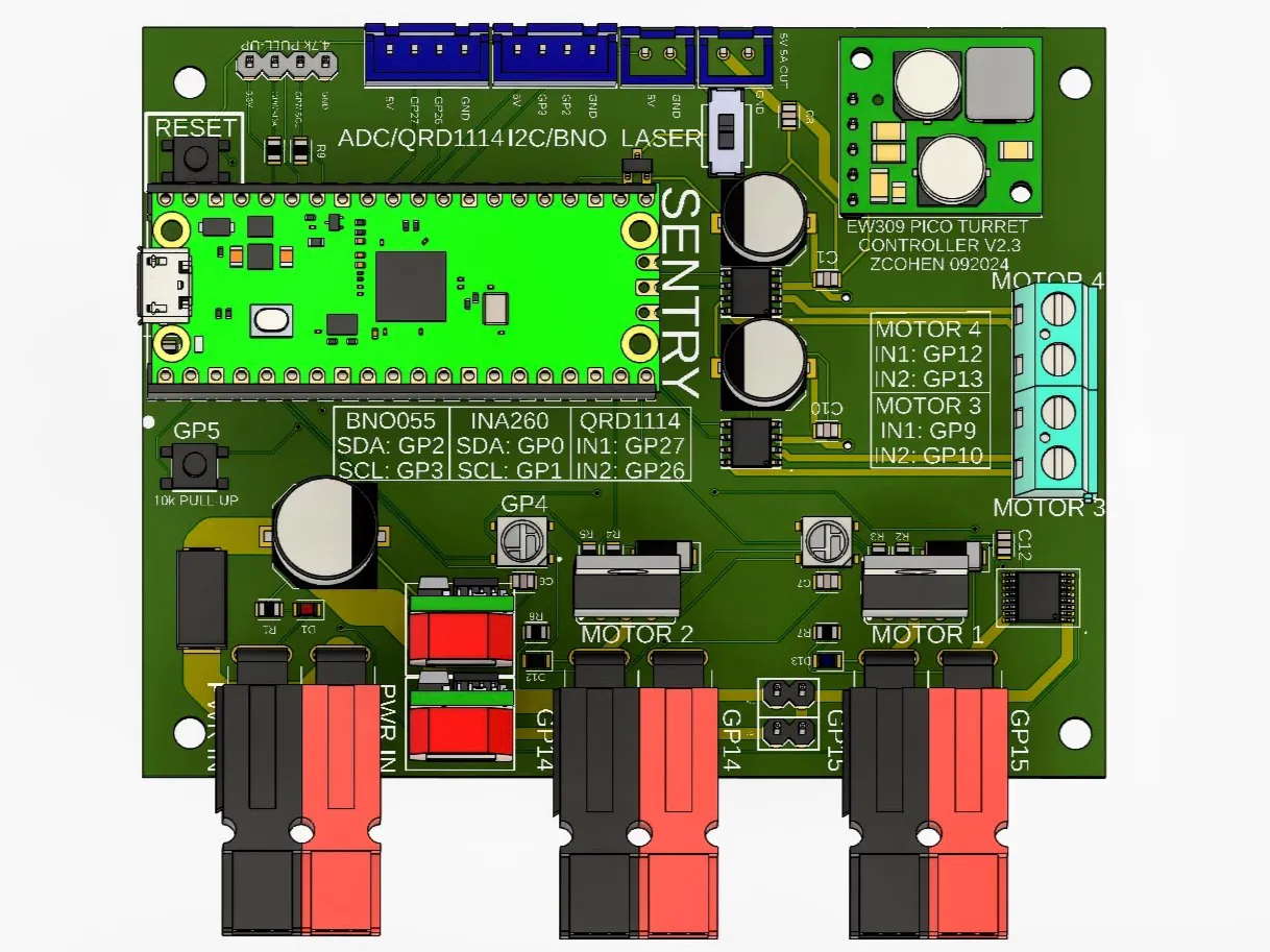
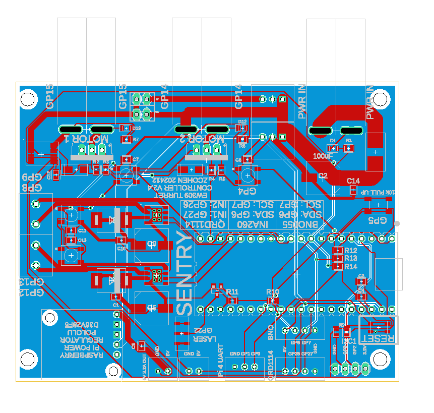
PCB layout
Labeled PCB
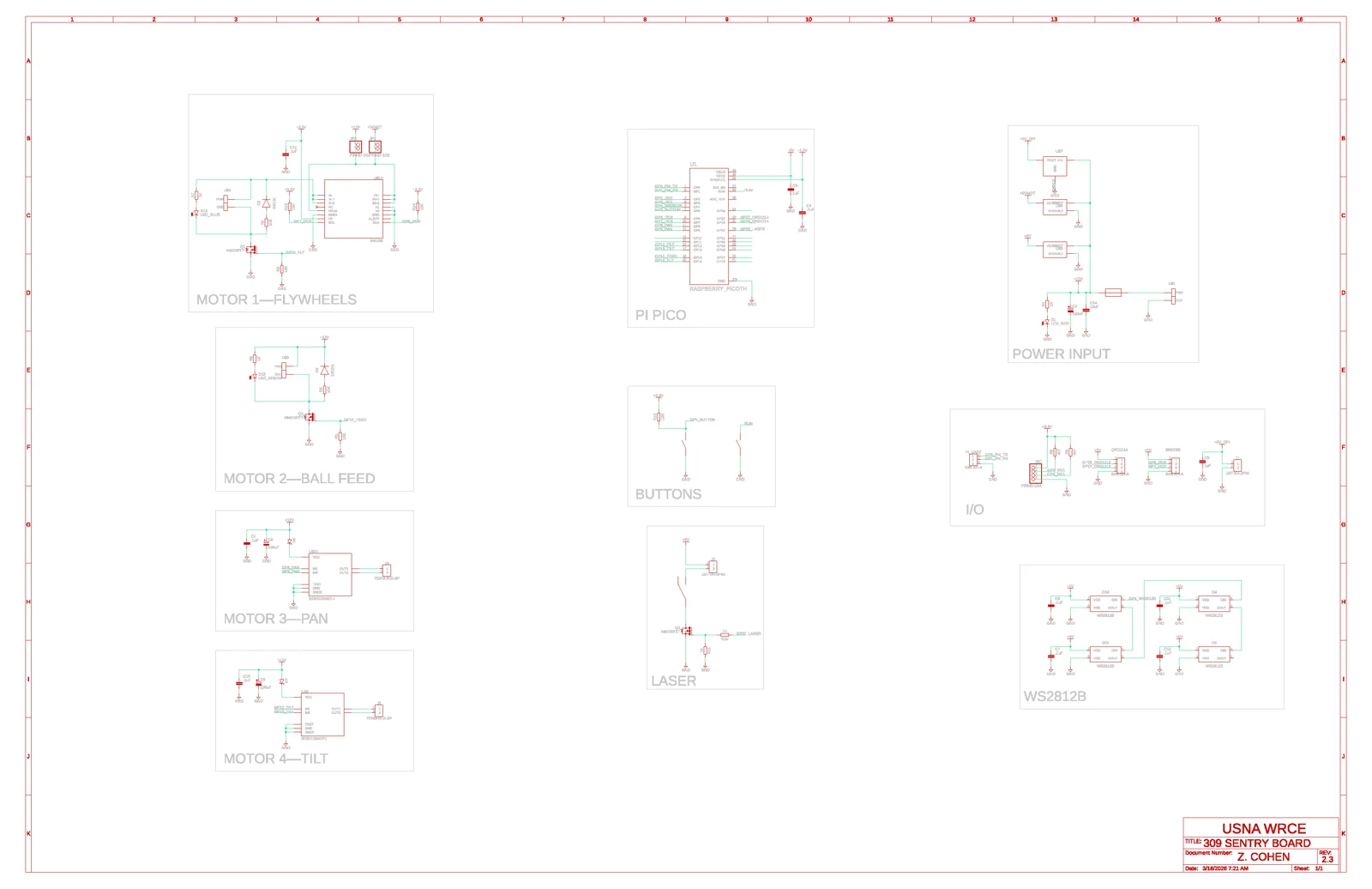
Electronics schematic
Testing & Verification
- Bench testing and bring-up were performed using logic analysis, current monitoring, and iterative firmware tuning.
- Flywheel current sensing was verified as a projectile-event detector — current spikes provide shot counting without dedicated sensors.
- The platform's classroom deployment (100+ students per year at the U.S. Naval Academy) exercises the integrated system across repeated build-and-run cycles.
Lessons Learned
- Separating high-level control from real-time actuation simplifies system behavior and makes debugging significantly easier.
- Current sensing can serve as a reliable proxy for mechanical events when adding dedicated sensors would increase complexity.
- Integrating multiple motor-driven subsystems requires careful sequencing and state management to prevent unexpected interactions between actuators.
- Early bring-up instrumentation (current monitoring, logic analysis, and serial diagnostics) greatly reduces iteration time during firmware development.
- Designing the control board with spare interfaces and expansion capability makes it easier to add sensors and experiment with new control strategies.
What comes next
The deployed V3 platform established the mechanical, electrical, embedded, and controls architecture described above. A separate V4 roadmap explores a ground-up redesign — layered perception, compute, control, and safety domains — carrying forward the lessons from V3 deployment. V4 is planning-stage work, not a shipped system.